Direct Digital Lambda (DDL)
Micro-Controlled Wide-Band Exhaust-Gas-Oxygen Sensor
Copyright © 2000-2002
Bernd Felsche , Perth, Western Australia.
This page discusses the use of a microcontroller (µC)
close-coupled to a wide-band lambda probe (O2 sensor)
to divest details of sensor operation from an engine management
system which really only wants to get feedback about the
air-fuel-ratio.
Digital techniques employed in the proposed system greatly simplify
analogue circuitry otherwise required to drive the sensor and
to provide more latitude for control, diagnostics, testing,
calibration and tuning.
Cell temperatures are measured directly by alternating-current
pulses.
The previous approach was to use the heater
resistance as an indicator of cell temperature.
Direct measurement is preferable as cell temperature determines cell
performance characteristics.
|
The proposed method arises primarily from DIY-WB
discussions in the DIY-EFI
mailing list (and off-list with other list members) and is a logical
extension of prior art and therefore not patentable in a sane world.
A
DIY-WB project exists that provides an interface to a
NTK/Honda-type wide-band O2 sensor.
Take a look at that if you're simply looking for a convenient,
working, analogue interface.
|
The owner of the Copyright © hereby grants free use of the idea
on the understanding that any development be contributed to
DIY-EFI projects.
The author would like to thank the following
DIY-EFI
list members for taking the time to discuss issues and to provide
pointers to further sources of information.
- Chris Conlon
- Dan Meyer
- Jörgen Karlsson
- and the rest for keeping the information out in the open.
A separate DDL mailing list has been established.
Disclaimer
I am not an electronics engineer. I'm a mechanical engineer.
Any information on this page is used at your own risk.
DDL Advantages
-
The hardware required is relatively available, cheap and simple.
-
The control logic resides in firmware and can be updated with no
change to on-board hardware.
-
The interface between sensor and ECU is 3-wire.
-
Small signals can be kept close to the sensor, reducing the effect
of noise and signal loss.
-
Full pump EMF encourages maximum ion velocity for improved response.
-
Constant, active ion exchange at stoichiometric increases sensitivity.
-
Cell temperatures are measured directly for improved accuracy
and control of the heater power.
-
Exhaust gas temperature metric available from cell temperatures and
heater power.
-
Sensor and circuit calibration parameters in firmware and the
µC is in-system programmable.
-
The hardware is potentially self-calibrating with external
instrumentation provided only for measuring probe temperature
(and actual exhaust gas composition if required).
-
Arbitrary heater ramp-up is possible.
-
Copious interfaces including RS-232 to a portable computer possible
for tuning and development.
-
The µC can compensate for and report sensor age by monitoring
the actual pump current during a current pulse and the time-response
of the Nernst cell.
-
A sensor fault of any sort can be signalled to the engine
control unit (ECU) by encapsulating error codes within the
communications bit-stream; or by using a spare I/O pin of the
µC for an explicit alarm.
A Wide-Band O2 Sensor
Very little hard, detailed information about how the sensors
are supposed to be driven is readily available.
A summary of relevant information is collected
here.
(Updated October 26th, 2001)
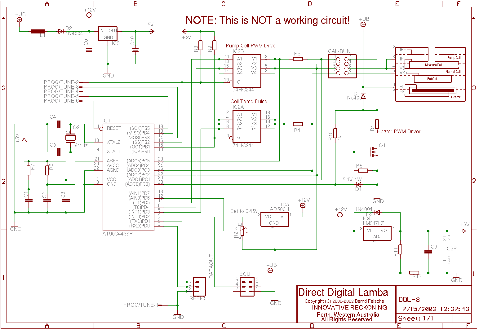
Circuit Details
A sample design is composed of an Atmel AT90S4433 in conjunction
with a Bosch wide-band lambda sensor.
The recently-announced Atmel ATMega8 has more on-chip features and
higher clock rates, so provides a ready upgrade path if the chip
AT90S4433 proves to be marginally insufficient.

Click image for larger view,
or shift-click to download either the
gzipped Postscript (56k) or the
Adobe-PDF (112k) version.
A sample board layout
illustrates the low component count and small size.
Gzipped Cadsoft Eagle
schematic
and board are available.
The circuit shown is for discussion only and is incomplete!
There is no software yet to operate the sensor.
The µC is an 8-bit RISC-based CPU with 6-channel, 10-bit ADC,
with a total of 20 I/O pins, UART, one 8-bit timer/counter, one
16-bit timer/counter, a watchdog timer, in-built PWM on the 16-bit
counter, an analogue comparator and internal brown-out detection.
There's 4K bytes of flash for program memory, 256 bytes of EEPROM
and 128 bytes of SRAM.
Flash and EEPROM are in-system-programmable via a serial peripheral
interface (SPI).
Various power-saving modes are supported; keeping SRAM alive with
only a few micro-amps.
Pump Cell Drive
The pump cell is driven by a virtual H-bridge switched by
pulse-width-modulation (PWM) from two pins (PD4 and PD5)
of the µC.
A member of the DIY-EFI suggested the drive method; employing a
74LS244-type bus driver chip to provide the necessary current
sources and sinks as the µC cannot source sufficient current.
Another contributor suggested pairing (otherwise unused) outputs of
the driver for improved drive performance.
Later generations of the µC are capable of sourcing sufficient
currents, but the voltage that that would present to the µC's
input pins at certain stages would be in excess of the rated input.
A 74AS244 is shown, but just about any 74*244 equivalent that will
operate from (approximately) 3V should work at the low speeds of the
circuit.
The low voltage is chosen so that the maximum voltage presented to
the ADC inputs of the µC will be below the 5V rail.
An AC part is a reasonable option.
The driver must be able to sink or source at least 10 mA.
The VOH and VOL do vary between
versions, but an acceptable component should be available, given
that the NTK controller only outputs ±2V.
As the µC is capable of taking relative measurements, the
voltage losses through the driver can be compensated.
Component choice is reduced to a question of supply voltage,
reasonable availability and moderate efficiency.
Pump current is reversed by alternating drive pins on the input to
the driver, and gating the latch to alternate the current flow
direction.
The latch is biased to 5V so that there is no drive current unless
the µC is actually running.
A RESET causes all I/O pins to tristate to high-impedance.
The driver is powered from a reduced-voltage rail.
This allow the Nernst cell voltage, which floats
above the pump cell's bias be measured almost all the time, even
when the potential on the pump cell has been reversed.
A maximum of (about) 3V is applied at the pump cell; the Nernst cell
voltage may be 1.1V higher.
The AVR's ADC and analogue comparator require that the voltage to be
measured remains below AREF; its analogue reference voltage (and
full-scale for the ADC) and below Vcc + 0.5V.
Average pump current (Ip) is determined by the
nett pulse-width of current flow through the bridge.
Various strategies are immediately obvious and the advantages of
pulse-width modulation (PWM) in conjunction with alternating
current through the pump cell are discussed in the literature.
A notable benefit is the expected improvement in cell
response around stoichiometric AFR where the average pump cell
current is zero, but equal amounts of gas are pumped in and out.
By using PWM techniques and alternating cycles of equal charge, the
measurement cell is continuously pumping ions; in contrast
with a constant-current drive which would rely on random diffusion
to sense any variation in gas composition.
Reference Cell
The µC balances the voltage at the reference cell against the
required value of 0.45V.
The cell's voltage will switch just like a conventional lambda probe
as the composition of the gas (partial pressure) at the Nernst cell
changes in response to the action of the pump cell.
Measurement of the cell voltage is by subtracting two voltage
measurements at pins PC2 and PC3 as the cell floats to
provide for periodic current reversals for cell temperature sensing.
One of the previous limits in DDL was the ADC delay for determining
the Nernst cell voltage.
It came to mind during that discussion with list members that the
AVR has a perfectly-adequate analogue comparator on-chip and that
this could be used to detect a swing from stoichiometric (0.45V)
almost instantaneously.
The deviation from the nominal voltage, and its direction could be
used to determine the pump current direction required to re-balance
the Nernst Cell.
The schematic shows a 0.45V constant-voltage device "riding" on the
virtual ground with its output going to one input of the comparator,
and the Nernst signal going to the other comparator input.
An AD580 was chosen as a voltage reference due to ready
availability; the supply voltage from the regulated 5V rail would be
marginal due to the necessary voltage drop in the device to maintain
the nominal output voltage above the floating ground.
Sensing bandwidth increases correspondingly.
Response to a voltage change at the Nernst cell is as little as 4
µC clock cycles when receiving an interrupt from the
comparator, compared to several hundred cycles for ADC conversion
and comparison.
The comparator's effective hysteresis is less than 10 mV.
Heater Drive
A power-FET is used to PWM the current through the integrated heater
of the sensor.
The pulse-width is determined in software.
The approximate current through the heater is measured by the
voltage drop across sense resistor R1.
R1 is chosen so that a cold sensor in series with the sense
resistor, will present a voltage below the clamp voltage at the
µC's ADC input when the FET is turned on.
R1 must also not be so low that it will cause excessive current to
be drawn through shorted heater terminals.
µC heater current measurement can be used to continuously
verify that the heater is still intact.
High-side heater drive is preferable but would be more expensive due
to the charge pump required to turn the FET on hard from logic level.
Suitable chips to drive low-cost, efficient FETs from logic level
are either rare or expensive; or both.
A relay or circuit breaker could also be employed to protect the
circuit but an in-line, 3 Amp fuse on the battery lead feeding the
controller is much simpler, though limiting the maximum heater
power.
Current is approximate as there are insufficient ADC ports on the
µC to measure the actual battery voltage.
Approximate measurement is sufficient to get the heater into the
nominal operating temperature range, within which closed-loop
temperature control is expected to be by measurement of cell
temperature.
Sensor temperature change is limited to 50 K/second by software.
The heater power can be logically "capped" to never exceed that
rate, even if the sensor were mounted in an insulated chamber.
A resistor is used to bleed off any charge at FET gate which might
otherwise cause it to become wedged on, especially when the
µC's output is tri-stated due to a reset.
The high-current diode protects the FET against voltage reversals.
This may be superfluous for the resistive load of the heater.
A Zener diode and series resistor protect and clamp the analogue
input to the µC in case the heater terminals are shorted.
A small amount of current (approximately 50mA at full battery
voltage) will flow through the heater with the FET turned off.
Analogue to Digital Conversion
A precision voltage reference could be used as a reference to the
µC's internal analogue to digital conversion (ADC)
circuitry.
The voltage rails will then not have to be regulated as accurately,
which is difficult anyway due to the pulse driving of the
implementation.
The main current consumers are however isolated.
The pump drive IC operates off its own regulated voltage rail and
the heater is operated directly from the battery.
Interfacing
The engine's ECU interface can be by single-wire,
but the ECU connector shown has provisions for power and ground as
well.
This connection is convenient as it's no more complex than a 3-wire
setup for switching lambda sensors with heater.
It's entirely possible that the existing wiring harness could be
employed.
As the µC has a UART, the addition of a level-driver chip
(e.g. MAX232) would allow the µC to communicate directly with
a portable, external computer.
A serial-programming interface (SPI) is also brought out to a
connector on the sample schematic.
An external programmer could then update the firmware in the
µC while it's in-circuit.
A header block is shown on the schematic to allow an in-system
programmer to be connected without fear of damaging the sensor if
connected.
A CMOS switch could be used instead as described in Atmel
documentation because the lines concerned are used only to source or
to sink currents when measuring the temperature of the Nernst cell.
Mode of Operation
Lambda Sensing
By sensing the voltage of the reference cell, the µC decides
on the width of current pulses to push and pull through the pump cell.
Using the 16-bit timer-counter of the µC provides up to 10-bit
PWM resolution in hardware, more than enough for application.
The schematic shows a short from the OC1 pin to INT1 so that the
µC can put PWM outputs on the correct transistor pair without
additional external components.
As well as a physical limitation of pump current, the maximum
average pump current can be limited according to stored parameters
within the µC's EEPROM and/or flash memory.
Calibration constants within the µC map the pulse width
to a lambda value.
This can then be transmitted to the engine management system as
a bit-stream or fed into a serial DAC (not shown) for a conventional
analogue interface to an engine management system.
Lambda values from 0.7 to 4.0 are usually considered interesting.
These could be mapped linearly to an 8-bit serial data stream
ranging from 1 to 254 (extremes used to indicate special conditions
to the ECU) with each increment representing a change in lambda of
0.013.
A digital output of 24 would then be equivalent to lambda=1.0
A change of 1% is detectable and hence it's possible to operate
within a narrow window to assist catalytic conversion.
The nett pulse width for the pump cell is determined by a software
providing for rapid response to perturbations and reducing long-term
drift.
Input to the control loop is the Nernst cell voltage which remains
nominally-fixed at 0.45V.
A fake lambda value can be provided to external circuitry
until the sensor reaches nominal operating temperature, or in the
event of a sensor fault.
Cell Temperatures
An accurate indication of temperature is provided by the cells
themselves.
Cell resistance is calculated by passing a nominally-constant test
current through the cell to measure its resistance.
US Patent 6,120,677 describes using the pump and reference cells'
resistance to determine temperature.
The pump cell drive described above is already capable of allowing
the necessary measurements to take place.
Pins PC3, PC4 and PC5 measure the voltage across the cell as well as
the drop across the current-sense resistor.
|
The provision of three analogue inputs per sensor provides precision
information about the current and voltage levels for determining
resistance.
Note that two cells share a common pin on the sensor's connector.
As the circuit switches are driven to saturation during pulse-width
modulation, the voltage levels at the source and sink are defined by
those components, so they are known to some precision without any
measurement having to take place.
Cell resistance can be determined by one analogue measurement
at the junction of cell and sense resistor;
which has the reduced likelihood of aliasing (although that is in
any case minimal as the characteristics are unlikely to change
appreciably in the 140 µs or so it takes to sample 3 values).
Manufacturing tolerances can be compensated for by a procedure after
assembly.
Setting jumpers on board can allow the µC to measure and store
correction factors for resistances.
An example of this is described below in the section on Calibration.
Component drift is another issue.
It is probably a good idea to calibrate at nominal operating
temperature.
|
The preferred PWM method (similar to that in Patent 5,312,538) can
be over-loaded to perform resistance measurement without
disrupting normal pump-cell operation.
Nernst cell voltage sampling on the other hand, will have to be
suspended for about 1.5 milliseconds during temperature measurement.
The µC's push-pull drive for the Nernst Cell shares one
pin with the SPI which is no real compromise because the latter is
used only for programming the device when it's off-line.
A current reversal of equal charge is necessary on the Nernst
cell as it will otherwise remain biased in one direction for a
significant time.
The reversal reduces the recovery time from around 16 milliseconds
to 0.5 milliseconds.
As the pump cell is to be continuously driven by suitable
pulses, the biasing problem is eliminated.
Pump drive must be coordinated as the pump and Nernst cells
share a single connector pin.
It appears likely that the timing of resistance measurement of the
Nernst Cell can be based on cycling of the pump cell, allowing the
pump to continue operating.
Literature indicates that the cell temperature varies relatively
slowly; of the order of 3°C per second, so such measurements
aren't necessarily frequent or disruptive if the control logic takes
the time constants into account.
Heater
When the system is started, the pulse-width can be ramped-up
according to the cell temperatures as evident from their resistance.
The AVR's 8-bit timer-counter is used to synthesise PWM as this
particular µC supports only one PWM in hardware,
The pulse width for the heater is also to be determined by a
software algorithm with knowledge of cell temperatures determining a
gradient to define the heater output required.
Some literature indicates that the sensor should operate at a
temperature above that of the exhaust gas for maximum precision.
If the pump cell (exposed to exhaust gases) is at a greater
temperature than the Nernst, then heater output has to increase
because the exhaust gas is hotter; up to the limit of operating
temperature.
If, on the other hand, the Nernst cell is slightly hotter than the
pump cell, then there may be sufficient heating.
However, a colder pump cell would indicate that the exhaust gas is
cooling the pump cell (no surprises here) and that the heater output
can be lowered as long as both cells are above the minimum nominal
operating temperature.
The cell temperatures and heater drive can be combined to provide a
metric of exhaust gas temperature.
Although the pump cell is nominally at exhaust gas temperature as a
first-approximation, it may be slightly cooler or hotter than the
surrounding gas stream.
And indication of which and its magnitude is determined by the
temperature gradient, the heater power and thermal calibration
constants.
Calibration
Calibration precedures can be triggered by external events; the
DATAOUT line on the ECU port could be pulled low or high to cause
the µC to start listening for commands on the UART (serial)
interface.
- Circuit Components
A jumper block is provided at the sensor interface to facilitate
self-calibration of the circuit for the current-sense resistors in
the circuit.
The respective cells are taken out of circuit and the
controller-side terminals bridged.
The µC is able to determine that it's in calibration mode by
the voltage levels present and can store appropriate correction
factors in EEPROM.
- Lamda Sensor Temperature
Other calibration to match the controller can be performed by
allowing the sensor to heat slowly in free air with power modulated
to the heater.
Once the cells begin to respond, the heater output is then regulated
to maintain the Nernst cell resistance.
The pump cell resistance will subsequently stabilise and allow
respective temperature calibration constants to be preserved.
Repeating this for several temperature points provides a useful
mapping.
If temperature-measurement facilities are available, then the
operating limits can be programmed according to temperature.
Once temperatures are known and can be measured internally,
the heat time-constant for heater input to the respective cells
can be determined for use in control.
- Exhaust Gas Composition
Once temperatures have been set, the pump current values can be
mapped to real lambda values.
This requires exposing the probe to gases of known composition and
identifying the corresponding pump current values.
The mapping could be recorded externally for subsequently flashing
into the µC or internally if there are enough EEPROM slots
available.
Of course the latter is preferable but it may require the AVR to
interpolate between a smaller set of values when calculating its
output.
Last updated July 15th, 2002
Copyright © 2000-2002
Bernd Felsche , Perth, Western Australia.