
Click Image see larger PNG
or here for a large (200+kb) JPG should you fail to see anything above.
Shift-Click to download the zipped Postscript file or the Adobe-PDF version.
The circuit shown is for illustration only and is incomplete!
|
The proposed method arises from DIY-EGOR discussions in the
DIY-EFI mailing list and is a
logical extension of prior art and therefore not patentable in a
sane world.
A DIY-EGOR project exists that provides an interface to a Honda-type wide-band O2 sensor. Take a look at that if you're simply looking for a convenient, working, analogue interface. |
The owner of the Copyright hereby grants free use of the idea on the understanding that any development be contributed to DIY-EFI projects.
The circuit shown is for illustration only and is incomplete!
The µC is an 8-bit RISC-based CPU with 6-channel, 10-bit ADC as part of total of 20 I/O pins, UART, one 8-bit timer/counter, one 16-bit timer/counter, a watchdog timer, in-built PWM on the 16-bit counter and internal brown-out detection. There's 4K bytes of flash for program memory, 256 bytes of EEPROM and 128 bytes of SRAM. Flash and EEPROM are in-system-programmable via a slave processor interface (SPI). Various power-saving modes are supported; keeping SRAM alive with only a few micro-amps.
The Bosch wide-band sensor (LSU) is actually comprised of four distinct sections:
Very little hard information about how the sensors are supposed to be driven is readily available. The pump cell is used to pump gases in or out according to the output of the reference cell. The pump current required to balance the reference cell provides a measure of lamba, the fuel-air ratio.
An integrated heating element is used to maintain a minimum cell operating temperature of 600 C.
Any data referred to herein are based on the following references
and should not be applied to any other type of sensor.
References (German):
English equivalents (the author has not seen these books):
The booklet describes the application and use of the sensors, omitting any crucial numbers required for DIY. You can download it from http://www.sae.org for a small charge or purchase it through another source such as http://www.rb.com. Note that much of what appears in the ME-Motronic instruction booklet appears in the Gasoline Engine Management book.
Pump Cell DriveThe pump cell is driven by a virtual H-bridge switched by pulse-width-modulation (PWM) from four different I/O pins of the µC. Half the H-bridge is inside the µC as it can sink up to 20mA; more than adequate for the pump cell.Pump current is reversed by switching alternate source transistors and draining through a corresponding µC pin. This is an improvemnt over the previous version of the circuit not only because it reduces the component count, but also because of inherent circuit safety in case of a µC RESET. A RESET causes all its I/O pins to tristate to high-impedance. The FETs input capacitance would have allowed the transistor to sypply an current for an indeterminate period in that event. With the drain side of the bridge in the circuit, the input high-impedance effectively blocks any current through the pump cell. Average pump current (Ip) is determined by the pulse-width and the direction of flow through the bridge. Reference CellThe µC balances the voltage at the reference cell against the required value. The reference cell will switch just like a conventional lambda probe as the composition of the gas in the Nernst cell changes in response to the action of the pump cell.Heater DriveA power-FET is used to PWM the current through the integrated heater of the sensor. The heater's internal resistance is used to determine its temperature, measured by use of a sense-resistor R1 during a pulse.Calibration for heater supply-voltage variation is facilitated by resistor-divider pair R4/R5. |
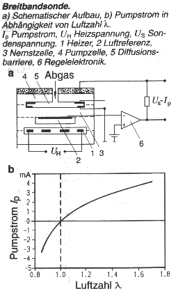
Illustration from (German) Bosch Automotive Handbook |
A recent patent describes using the pump and reference cells' resistance to determine temperature. The pump cell drive above is already capable of allowing the necessary measurements to take place. Two analogue inputs to the µC provide a means of measuring actual voltages across the cell and sense/limiting resistor which, with the current-sense voltage, allow a determination of cell resistance.
Obtaining a similar reading from the reference cell would require some external circuit changes to allow that cell to "float" as a reversal current is necessary to allow the reference cell to recover rapidly from resistance measurement.
The heater temperature can therefore be driven more accurately with knowledge of heater element and pump cell temperatures determining a gradient without additional componentry.
A µC with more ADC channels would facilitate measuring all three resistances and hence temperatures. The µC shown is capable of sourcing up to 3mA, so some the necessary push-pull drive should be possible by utilising the I/O pins currently annotated exclusively for SPI; and the requisite additional voltage sense connections moved from the heater. The heater's temperature is "superfluous" as we are primarily concerned with maintaining cell temperatures,
Two additional components would be required; a switch circuit to allow the SPI pins to be used for I/O when not employed for in-system programming, and a current-sense resistor in series with the cell.
As the µC has a UART, the addition of a level-driver chip (not shown) would allow the µC to communicate directly with a portable, external computer.
A serial-programming interface (SPI) is also brought out to a connector on the sample schematic. An external programmer could then update the firmware in the µC while it's in-circuit.
Calibration constants within the µC scale the pulse-width and direction to a lambda value. The value can then be transmitted to the engine management system as a bit-stream or fed into a serial DAC (not shown) for a conventional analogue interface to an engine management system.
A fake lambda value can be provided to external circuitry until the sensor reaches nominal operating temperature, or in the event of a sensor fault.
There is also the possibility of being able to measure the pump cell resistance as mentioned in Patent number 6,120,677 (NGK) to ascertain the temperature of the cell for a more-accurate indication of temperature than the heater's resistance. Two ADC connections at the outputs of the H-bridge measure the voltage present, and the current-sense resistor can be used to calculate cell resistance.
Further searches of the US Patent database show numerous, possibly useful ideas which could be applied easily by close-coupling of the µC to the sensor.
The 8-bit timer-counter is used to synthesise PWM as this particular µC supports only one PWM in hardware,
Lambda output is enabled while the sensor temperature is within nominal operating range.